Finding the bad link in an SDH network using BIP counters
Posted June 15th 2017
SDH/SONET has relatively powerful mechanisms for detecting transmission errors, far better than E1/T1 lines. We can use those mechanisms to figure out which optical link in a network has errors. This post shows which parts of the network can see errors in various cases—and which parts cannot.
SDH error detection and counters
SDH packs data into virtual containers (VCs). VCs can be nested, for instance an E1 is transported using a VC-12 and up to 63 VC-12s can in turn be packed together into a larger container called a VC-4. Each of those containers has parity bits so that the receiver can see if the data was damaged in transit. These parity bits are called a bit interleaved parity (BIP).
Each add/drop multiplexor (ADM) in an SDH network keeps count of the number of errors in each BIP it checks. Normally, the ADM will only check the BIP in a container it unpacks or re-packs. Each ADM also sends reports of the BIP error counts backwards on each link. Such a report is called a remote error indication (REI).
By looking at BIP counters and REI counters in various parts of the network, we can reason about the likely source of transmission errors.
A concrete example: case 1
On the left side of this network, we have 15 E1s. They are transported along the light blue path over to the right side of the diagram:
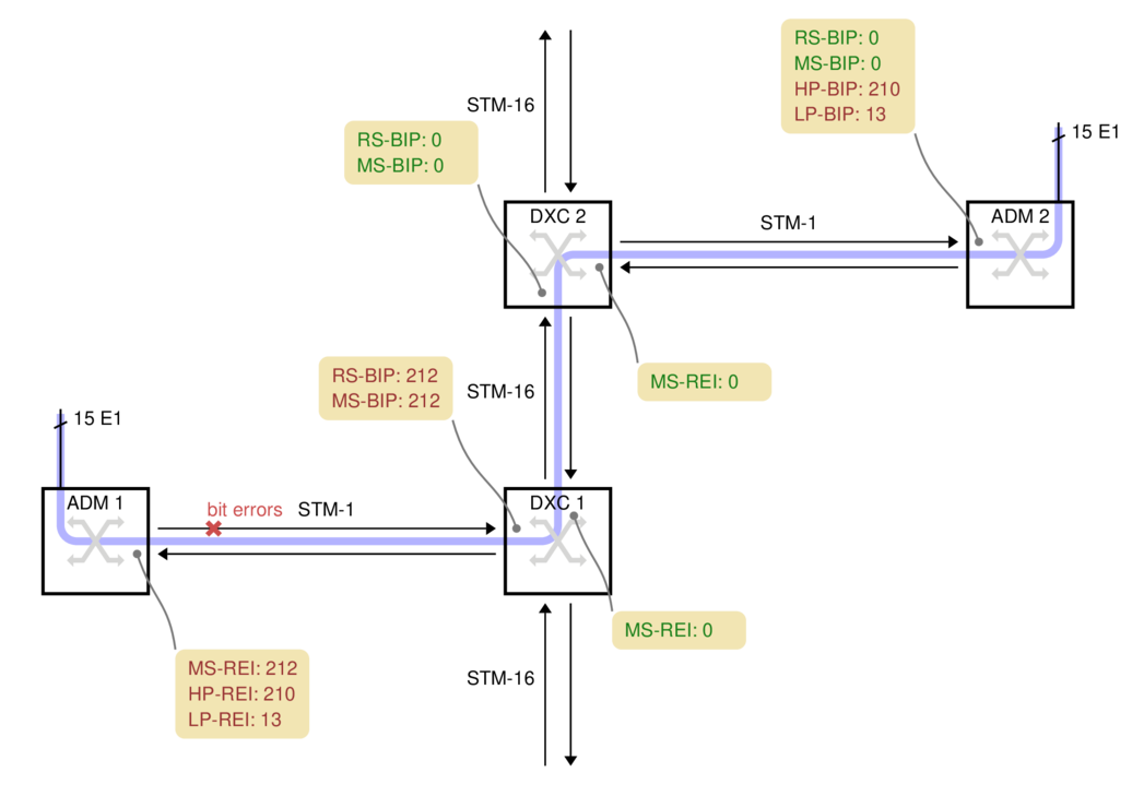
ADM 1
ADM 1 picks up 15 electrical E1s and packs them into 15 VC-12 containers. The VC-12s are packed into a VC-4 and transmitted over a 155 Mbit/s STM-1 optical link towards the operator's core network.
For this case, we're assuming the fiber between ADM 1 and DXC 1 has a problem which causes bit errors. The problem spot is marked with a red cross on the fiber. DXC 1 is in the best position to detect those bit errors since it is directly connected to the fiber with the problem.
DXC 1
DXC 1 is a high-capacity digital cross-connect which can forward data to the operator's 2.5 Gbit/s STM-16 ring. Some manufacturers abbreviate digital cross-connect system to DXC, others use DCS.
The DXC counts two types of parity errors on the incoming fiber: RS-BIP and MS-BIP (Regenerator Section and Multiplex Section Bit Interleaved Parity). Both count an estimate of the number of bit errors in (almost) the whole STM-1. In this example, 212 errors have been detected by both counters, the diagram shows them in yellow boxes.
DXC 1 also transmits the error counts back to ADM 1, as remote error indication (REI) values. They are shown in the yellow box below each node.
DXC 2
DXC 2 cannot report any transmission errors. The DXC's switching granularity is a whole VC-4, so it never unpacks the VC-4 or VC-12s to check the BIPs. DXC 2 just forwards an exact copy of the incoming VC-4.
ADM 2
ADM 2 unpacks both the VC-4 and all 15 VC-12s, so it can report the HP-BIP (High-order Path, Bit Interleaved Parity) and the LP-BIP (Low-order Path) errors. In this example, 210 errors were detected in the HP-BIP and 13 in the LP-BIP.
A more complicated example: case 2
In this example, two ADMs are connected in series on the left, with each one attaching several E1s to the SDH network:
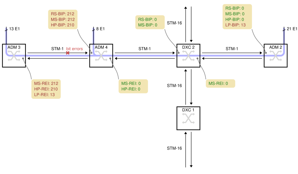
ADM 3 has 13 E1s which it sends rightwards. For this example, the bit errors are on the fiber between ADM 3 and ADM 4, marked with a red cross.
ADM 4 has a further 8 electrical E1s. It unpacks the 13 VC-12s from ADM 3, adds the 8 new VC-12s, makes a new VC-4 and transmits the result to DXC 2.
DXC 2 cannot report any errors because it just copies the incoming VC-4.
ADM 2 unpacks all 21 E1s, so it can see that 13 of the LP-BIP counters have errors, but 8 do not. Armed with a map of the network, this is often enough information to deduce where the problem is. There are no HP-BIP errors, however, because the VC-4 arriving here was made by ADM 4, whereas the transmission errors happened before ADM 4.
Practical Complications
All ADMs and DXCs are capable of counting the number of BIP errors down to the level above their switching granularity. But actually finding the value in the manufacturer's command-line or GUI is not always easy. On Corelatus equipment, the values are displayed on the on-board HTTP server, under SDH. They are also available via the CLI and API.
The names for the BIP error counters vary from manufacturer to manufacturer. Sometimes, the counter is named after the byte in the SDH frame the counters are carried on, i.e. B1, B2, B3 and V5 correspond to RS-BIP, MS-BIP, HP-BIP and LP-BIP, respectively.
When Corelatus equipment is used with SONET, it reports the counters using the standard SONET names, e.g. REI-L for what would be called MS-REI in SDH.
Using an optical splitter, you can always connect a Corelatus SDH Monitor 3.0 to an STM-1 link and see the BIP and REI counters at all levels. That provides more information about errors than just looking at a DXC's counters, partly because the Corelatus system can report BIP errors all the way down to VC-12 and partly because the Corelatus system can decode and record the data on E1/T1 timeslots. In case 2, the DXC does not report the LP-BIP errors because the DXC has no reason to unpack the VC-12s it is carrying, but a Corelatus system connected any of fiber links along the whole transmission path will report the LP-BIP errors and, optionally, decode SS7 or other signalling on individual E1 timeslots.
Permalink | Tags: GTH, telecom-signalling, SDH and SONET